JAPANESE / ENGLISH
JAPANESE / ENGLISH
Last updated on 05/7/2021
WDM is an abbreviation for Wavelength-Division Multiplexing, and is now one of the most widely used technology for high-capacity optical communication systems. Figure 1 schematically shows a typical WDM transmission system. At the transmitter side, multiple optical transmitters – each emitting at a different wavelength – individually send signals and these signals are multiplexed by a wavelength multiplexer (MUX). The multiplexed signals are then transmitted over one main transmission line (optical fiber cable). At the receiver side, the signals are de-multiplexed by a wavelength de-multiplexer (DEMUX) and sent to multiple receivers.
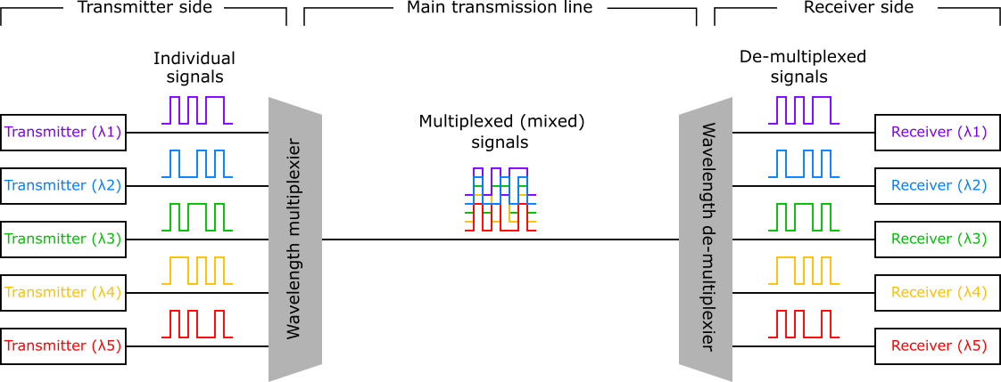
Figure 1: Schematic of WDM transmission system.
One primary advantage of using WDM technology is in reducing the number of fibers used in the main transmission line. The distance of an optical transmission line sometimes exceeds 1,000 km, and the cost of fiber cable manufacturing/deployment would become a serious issue if we need to install a high-fiber-count cable over a very long distance. Using WDM technology, (1) the number of fibers in an optical cable is reduced, and (2) the number of wavelength multiplexer/de-multiplexer basically remains the same no matter how long the transmission distance is. For that reason, WDM generally becomes advantageous as the transmission distance becomes longer.
In order to transmit optical signals over a long distance (> 100 km), optical fiber amplifiers are needed to compensate the loss of an optical fiber. As the gain bandwidth of an optical fiber amplifier is rather limited, a tight wavelength spacing is needed to put a large number of channels into the gain bandwidth. The dense WDM (DWDM) technology has been developed for a long distance transmission systems, fully utilizing the gain bandwidth of erbium-doped fiber amplifier (EDFA). EDFA has optical gain in the C-band and L-band, and for example, a total of 115 wavelength channels are transmitted in one fiber with 100-GHz (~0.8 nm) frequency spacing, as shown in Figure 2. Several different frequency spacings for DWDM applications are defined in ITU-T G.694.1, and an appropriate spacing is chosen depending on system requirements (total capacity, bit rate per channel, distance, etc.).
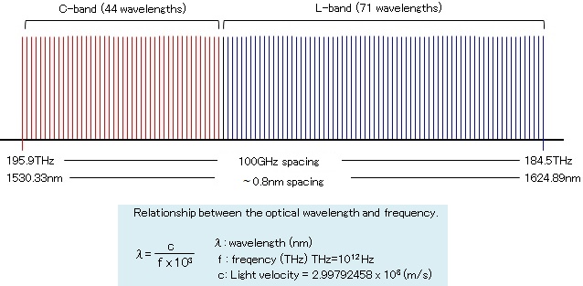
Figure 2: Center wavelengths of DWDM.
The need for a tight channel spacing in DWDM technology mainly arises from the relatively narrow gain bandwidth of EDFA (compared to the entire optical telecommunication bands). On the other hand, if the transmission distance is less than 100 km and no amplifiers are needed, a wider channel spacing can be an option. A wider channel spacing allows the use of inexpensive components such as:
and as a result, the total cost for installation and operation becomes less expensive. Such WDM systems are called coarse WDM (CWDM), and ITU-T G.694.2 defines one wavelengths allocation for CWDM systems, as shown in Figure 3. There are 18 center wavelengths with 20 nm spacing from 1271 nm to 1611 nm, covering the O-, E-, S-, C- and L-bands. All the 18 wavelengths are not necessarily be used, and in fact, it is very common to use:
This is mainly because many optical components (e.g. MUX/DEMUX and CWDM add-drop filters) are mass produced and widely available in the above wavelength ranges.
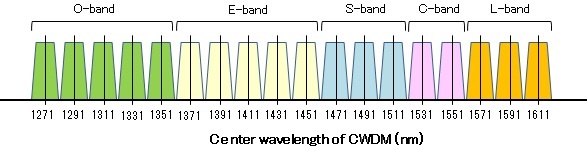
Figure 3: Center wavelengths of CWDM.
Telecom networks are roughly classified into three categories, the core, metro, and access networks (see Figure 4). The core network connects major cities (>100 km) and DWDM technology is often used. The metro network is used inside a metropolitan area, typically 50~80 km, and CWDM may be used. The access network rarely uses WDM technology at present, as the requirement for transmission capacity is much less than the core and metro networks.
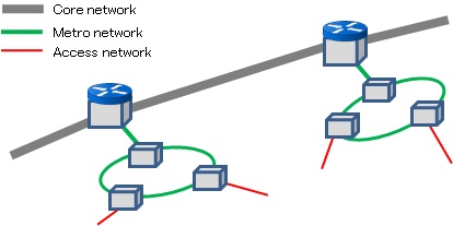
Figure 4: Schematic of telecom network.
Technological hurdles in high-speed datacom networks (e.g. data centers) are power consumption and space efficiency. High-speed telecom networks have been boosted by digital-coherent detection technology with a digital signal processor (DSP); however the power consumption is too big (>10W) and it is not realistic to apply the technology to a large scale data center. Traditional “direct detection without dispersion compensation” is preferred in terms of power consumption, and WDM technology in datacom is often used to enable high-speed transceivers in small size and with low power consumption.
For example, many 100G Ethernet transceivers – that are heavily used in data centers – use four-wavelength WDM in the O-band. Chromatic dispersion of the conventional single-mode fiber (ITU-T G.652 fiber) becomes zero in the O-band, and fiber dispersion is minimized. In addition, the four-wavelength WDM scheme reduces the bit rate per channel (100/4=25Gbps), which makes the dispersion tolerance four times larger than a single-channel 100Gbps system.
There are two choices for a set of four wavelengths in the O-band, namely CWDM4 and LAN-WDM. The wavelength ranges are shown in Figure 5 and 6, along with the maximum and minimum chromatic dispersion of the conventional single-mode fiber. The CWDM4 wavelengths are the same as those used in telecom CWDM, allowing the use of cost-effective optics developed for telecom applications. The LAN-WDM wavelengths are more tightly spaced than CWDM4 wavelengths, and are located nearly at the zero-dispersion wavelength of the fiber. This wavelength allocation enables 100Gbps transmission longer than 10km (e.g. 100GBASE-LR4 and ER4) without restricted by fiber chromatic dispersion.
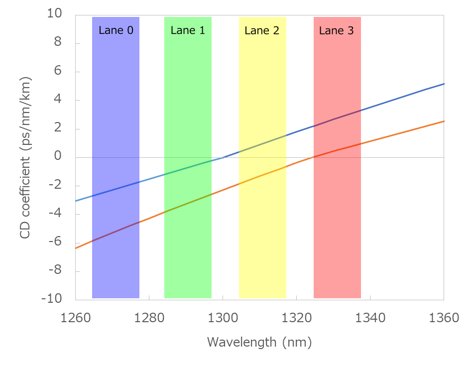
Figure 5: CWDM4 wavelengths.
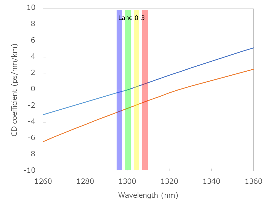
Figure 6: LAN-WDM wavelengths.
FiberLabs offers O-band amplifier (PDFA) for LAN-WDM, S-band amplifier (TDFA), C- and L-band amplifier (EDFA) for DWDM systems. We also offer optical fiber amplifier for CWDM systems using our proprietary fluoride fiber technology. CWDM amplifiers can be used to extend the reach in a specific part of a CWDM network, while being benefited from inexpensive optical components in the most part of the network.
FiberLabs also offers fiber-coupled light sources and optical tunable filter for test and measurement of optical components used in WDM networks.
Please visit our product page to check the specifications and performance.
| 850-nm-band | O-band | S-band | C-band | L-band | C+L-band | S+C+L-band | Full-band (O/E/S/C/L) | |
|---|---|---|---|---|---|---|---|---|
| Fiber amplifier | Bench-top | Bench-top Rack-mount OEM Module | Bench-top Rack-mount OEM Module | Bench-top Bench-top, HP Rack-mount OEM Module | Bench-top Bench-top, HP Rack-mount OEM Module | Bench-top 4-λ CWDM (rack-mount) Unidirectional BiDi, Booster BiDi, In-line | 8-λ CWDM (rack-mount) Unidirectional | N/A |
| ASE source | Bench-top | Bench-top OEM module | Bench-top OEM module | Bench-top OEM module | Bench-top OEM module | Bench-top OEM module | Bench-top | N/A |
| SLD source | Bench-top OEM module | Bench-top | ||||||
| LD source | Bench-top (Fabry-Perot) Bench-top (DFB) Bench-top (FBG-stabilized) | N/A | N/A | N/A | ||||
| Tunable filter | N/A | Bench-top | N/A | N/A | ||||