JAPANESE / ENGLISH
JAPANESE / ENGLISH
Last updated on 05/7/2021
Erbium-Doped Fiber Amplifier (EDFA) is an optical amplifier used in the C-band and L-band, where loss of telecom optical fibers becomes lowest in the entire optical communication bands. Invented in 1987 , EDFA is now most commonly used to compensate the loss of an optical fiber in long-distance optical communication. Another important characteristic is that EDFA can amplify multiple optical signals simultaneously, and thus can be easily combined with WDM technology.
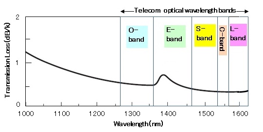
Figure 1: Optical telecommunication optical bands (EDFA operates in the C- and L-band).
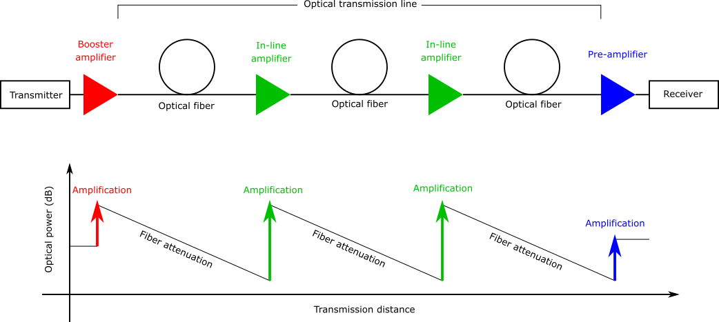
Figure 2: Booster, inline, and pre-amplifier EDFAs used in optical transmission line.
Before the invention of EDFA, a long optical fiber transmission line required a complicated optical-to-electrical (O-E) and E-O converter for signal regeneration. The use of EDFA has eliminated the need for such O-E and E-O conversion, significantly simplifying the system. This is especially of use in a submarine optical transmission, where more than a hundred EDFA repeaters may be needed to construct one link. The TPC-5CN (Trans-Pacific Cable 5 Cable Network), started its operation in 1996, is the first submarine optical fiber network which employed EDFA.
Figure 3 illustrates a simplified energy diagram of Er, showing how amplification takes place at 1550 nm. Two typical wavelengths to pump an EDFA are 980 or 1480 nm.
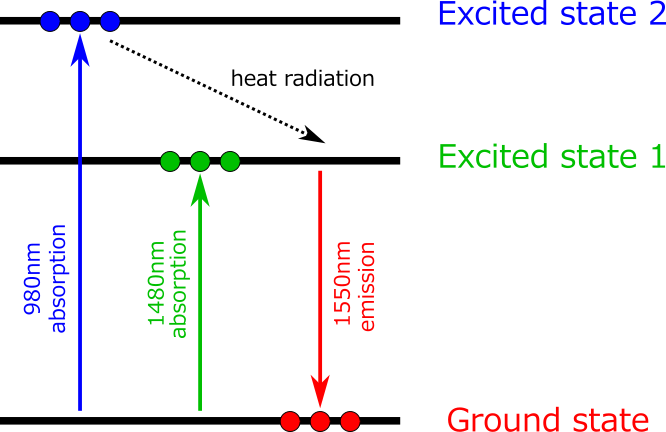
Figure 3: Energy diagram of Erbium.
When an EDFA is pumped at 1480 nm, Er ion doped in the fiber absorbs the pump light and is excited to an excited state (Excited state 1 in Figure 3). When sufficient pump power is launched to the fiber and population inversion is created between the ground state and Excited state 1, amplification by stimulated emission takes place at around 1550 nm. When an EDFA is pumped at 980 nm, Er ion absorbs the pump light and is excited to another excited state (Excited state 2 in Figure 3). The lifetime of the Excited state 2 is relatively short, and as a result, the Er ion is immediately relaxed to the Excited state 1 by radiating heat (i.e. no photon emission). This relaxation process creates a population inversion between the ground level and Excited state 1, and amplification takes place at around 1550 nm.
Since the first demonstration of a diode-pumped EDFA in 1989 , intensive effort has been made to make the pump LD highly reliable. Now high-power pump laser diodes at 980 nm or 1480 nm are both commercially available, and most EDFAs are pumped by laser diodes due to the compactness and robustness.
Figure 4 shows one common configuration of EDFA. The input signal is combined with the pump light by a WDM coupler and launched to the EDF. The pump light launched to the EDF creates population inversion and the input signal is amplified by stimulated emission. Isolators are placed both at the input and output, in order to stabilize signal amplification by eliminating unwanted back reflection from the output port, as well as to prevent the amplifier from operating as a laser. In this common configuration, the wavelength of the pump LD is locked close to the peak absorption wavelength of erbium (by an external fiber Bragg grating); the wavelength range is normally between 974 nm to 980 nm.
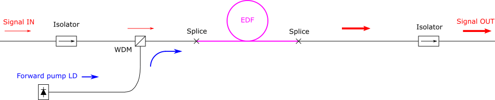
Figure 4: Common configuration of EDFA.
This section explains important optical characteristics of EDFA.
Saturated output power is the maximum output power from an amplifier when sufficient signal input power (typically around 0 dBm or higher) is launched to the amplifier. A booster amplifier typically operates under this condition, and thus saturated output power is an important characteristic for a booster amplifier.
Small-signal gain is the gain in an amplifier when the signal power launched to the amplifier is very small (typically around -30 dBm). A pre-amplifier typically operates under this condition, and thus small-signal gain is an important characteristic for a pre-amplifier.
Amplification by an EDFA adds some noise to the original signal – mainly due to amplified spontaneous emission (ASE) from the EDF – and thus decreases the signal-to-noise ratio (S/N ratio). Noise figure (NF) of an optical amplifier is a measure of degradation in the S/N ratio, expressed in dB, and lower NF indicates lower noise characteristic (theoretical minimum 3 dB). In general, ASE grows fast when the signal input power is low, thus NF is an important characteristic for a pre-amplifier (i.e. small input power). On the other hand, ASE is well suppressed when the signal input power is high, and the NF value measured at a higher input power has little importance. A typical NF value of commercial EDFA at a small signal input power is within the range of 5 to 7 dB.
When an EDFA is used for wavelength-division multiplexing (WDM) transmission, it would be ideal that all the WDM channels have equal gain. In reality, however, each of the channels has a different gain value and the variation is referred to as the gain flatness. Gain flatness is particularly important when many EDFAs are concatenated in an optical transmission line (e.g. submarine optical transmission), as the gain variation is accumulated in the EDFA chains and results in large signal power differences between the WDM channels. Gain flatness can be improved by, for example, modification of glass composition of the EDF (higher aluminium concentration) or the incorporation of an external gain-flattening optical filter.
Cladding-pumping configuration is a popular choice for high-power operation, and so-called “erbium/ytterbium co-doped” fiber amplifier is often used. In this scheme, ytterbium (Yb) is co-doped as a sensitizer to increase the absorption, as the absorption becomes much smaller in cladding-pumping configuration due to poor overlap between the core and pump light.
The operation principle of an Er/Yb co-doped fiber is shown in Figure 5. The Er ions are excited by the following two steps: (1) pump photons excite the Yb ions first, and (2) the excited Yb ions transfer the energy to the Er ions, raising them to the Excited state 2.
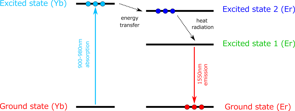
Figure 5: Energy diagram of Er/Yb co-doped fiber.
Of course, it would be more straightforward to achieve higher absorption by increasing the doping level of erbium. It is, however, well known that a higher erbium doping level (≥5,000ppm) leads to a poor amplifier efficiency, as interactions between two neighboring Er ions (ion pair) increase. Such interactions are much less significant for Yb ion pairs, and thus a higher doping level (≥10,000ppm) is allowed without sacrificing the amplifier efficiency. Most high-power EDFAs (typically ≥500 mW) use this configuration, and they are often referred to as EYDFAs.
Another benefit of ytterbium sensitization lies in its wider absorption wavelength range. Absorption wavelength of ytterbium extends down to 900 nm, thus wavelength locking of the pump LD is not necessary.
FiberLabs offers EDFAs in various wavelength coverage and product format. Please visit these pages if you are interested in our EDFA products.
| Wavelength | C-band | L-band | C+L-band |
|---|---|---|---|
| Full lineup | C-band EDFA | L-band EDFA | C+L-band EDFA |
| Individual product | Bench-top Bench-top, HP Rack-mount OEM Module | Bench-top Bench-top, HP Rack-mount OEM Module | Bench-top |