JAPANESE / ENGLISH
JAPANESE / ENGLISH
Last updated on 05/7/2021
Optical fibers are arguably the most widely used form of optical waveguide. Unlike other form of waveguides, optical fibers can be manufactured long and bendable, and thus are primarily used for a transmission media for optical fiber communication. Optical fibers are also used as an amplification media, i.e. fiber amplifiers and fiber lasers.
The history of optical fibers is believed to date back to mid 1800s, when an Irish physicist John Tyndall demonstrated light guidance in a fountain (see Figure 1). Light is guided in a stream of water by total internal reflection (TIR) even though the water stream is bent by gravity. This phenomenon highlights two very important features of optical fiber – long and bendable.
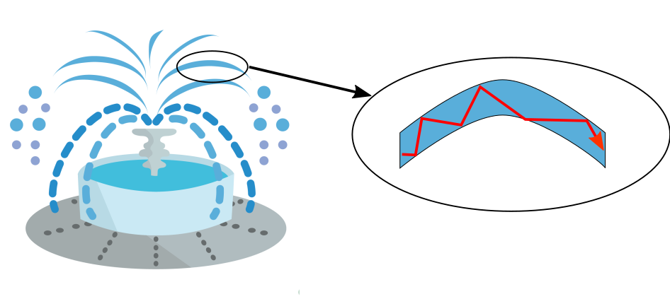
Figure 1: Light guidance in fountain by TIR.
TIR takes place at any interface between two materials with different refractive indices, not only at the interface of water and air. Figure 2 shows schematically the most basic form of a modern optical fiber. A core is embedded in a cladding and modifies the refractive index in the transverse (x and y) direction, and the modification is uniform in the longitudinal (z) direction. The refractive-index modification enables the transverse confinement of light in the core, and light is guided longitudinally in the core.
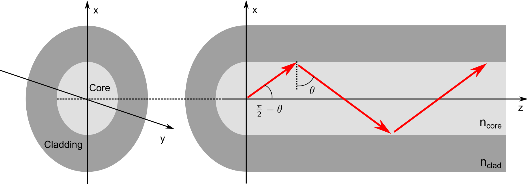
Figure 2: Schematic of optical fiber, and a ray confined in the core by TIR.
Figure 2 shows schematically, using ray optics, the light guided in the core by TIR. The refractive indices of the core and cladding are ncore and nclad, and a ray is travelling in the core with an angle θ. If ncore > nclad and θ is larger than the critical angle θc which is provided by
\(\displaystyle \theta_{\mathrm{c}}=\sin^{-1}\left( \frac{\mathrm{n_{clad}}}{\mathrm{n_{core}}} \right), \)
TIR takes place at the border between the core and cladding, and the ray is confined in the core. On the other hand, the power of a ray in the core rapidly decreases if θ is smaller than θc, because the ray is only partially reflected back at the border. The refractive index of the core has to be higher than that of the cladding, in order to guide light by total internal reflection.
The equation also suggests that a larger refractive-index difference between the core and cladding provides a smaller θc. A small θc allows for launching light into the fiber with a large angle ( \(\pi/2−\theta\) in Figure 1), enabling the launch of higher power density into the core. As a measure of the ability to accept light with a large launch angle, the numerical aperture (NA) of a fiber is defined by
\(\displaystyle \mathrm{NA}=\mathrm{n_{core}}\sin \left( \frac{\pi}{2}-\theta_{\mathrm{c}} \right)=\sqrt{\mathrm{n_{core}^2-n_{clad}^2}}. \)
This equation suggests an optical fiber with a higher NA allows the launch of light with a larger launch angle, therefore enables the launch of higher power density into the core.
There are two major types of refractive-index profiles – step index (SI) and graded index (GI) – and they are schematically shown in Figure 3. The core of a SI fiber has a uniformly raised refractive index profile, and that of a GI fiber has a continuously raised refractive index profile. The largest difference between these two types of optical fibers lies in the ability to maintain the pulse shape after propagation.
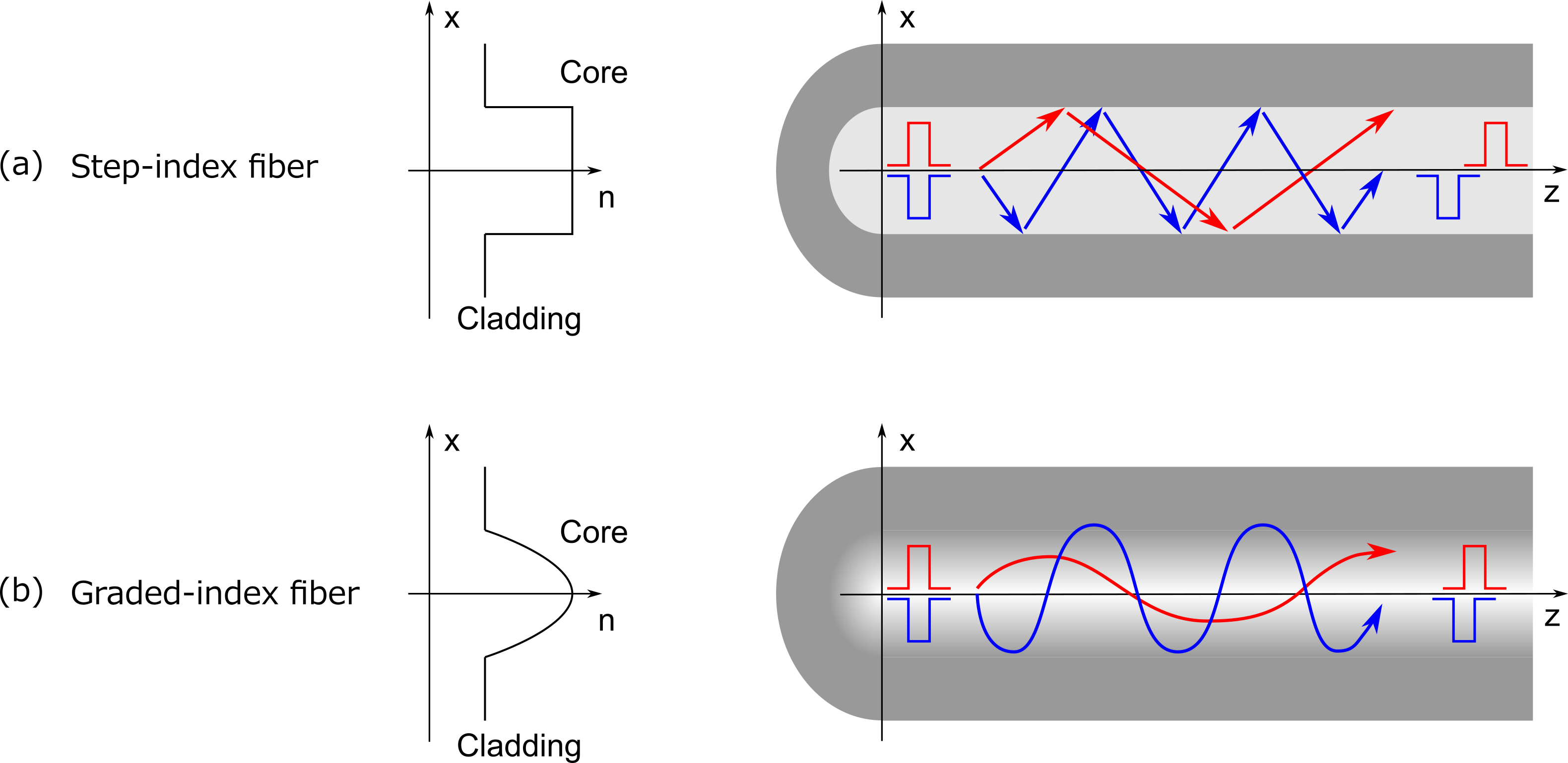
Figure 3: Light guidance in (1) step-index and (2) graded-index fiber.
When an optical pulse is launched into a SI fiber, the propagation velocity of the pulse is highly dependent on the incident angle. Figure 3(a) intuitively explains that the light launched at a larger incident angle (blue ray in the figure) propagates at a slower velocity, as the path length is longer. This is problematic for high-speed optical communication as the incident pulse shape is degraded at the output.
GI fiber was introduced in order to overcome this limitation of SI fiber. Figure 3(b) shows that, light launched at a small angle (red ray) mainly travels near the center of the core, and light launched at a large angle (blue ray) travels at the outer side of the core. The path length is still longer for the blue ray; however the blue ray travels at a faster speed than the red ray as the refractive index of the outer side of the core is lower than that of the center. The difference in the propagation velocity, therefore, becomes much smaller and degradation in the pulse shape is reduced.
The number of allowed optical paths in an optical fiber, called modes, depends on the refractive-index profile. If more than one mode is allowed to propagate in a fiber at a certain wavelength, the fiber is called a multimode fiber (at that wavelength). If only one mode is allowed to propagate, the fiber is called a single-mode fiber. A single-mode fiber has a relatively smaller core size compared to a multimode fiber, and only one propagation mode is allowed (see Figure 4).
It is theoretically possible to eliminate the modal delay in a multimode fiber by carefully tuning the graded index profile. In reality, however, small amount of modal delay always remains due to small variations in fiber fabrication. The small amount of modal delay is critical in high-speed and long-distance optical transmission, as even a small delay causes signal overlap between neighboring bits – the original signals can no longer be recovered at the receiver side.
The use of single-mode fibers in an optical transmission line fundamentally eliminates signal distortions due to modal delay, and thus single-mode fibers have now become the most widely used type of optical fibers in optical communications.
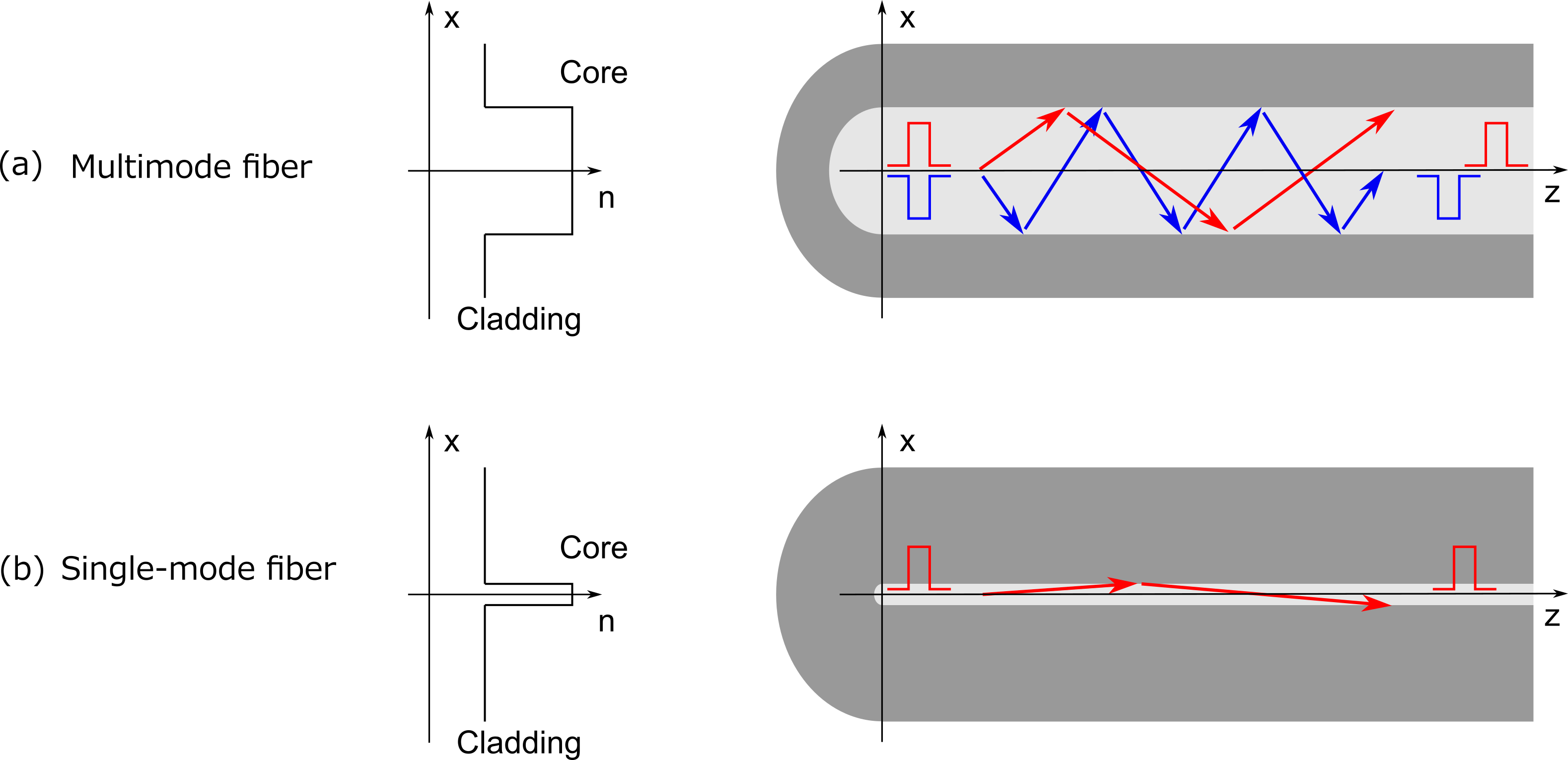
Figure 4: Multimode and single-mode fiber.
When light travels in the core of an optical fiber, the optical power is attenuated by scatterings, absorptions, longitudinal nonuniformity, etc. The attenuation of optical fiber is often shown in dB/km, and a typical loss value of standard optical fiber is around 0.17-0.35 dB/km in the optical communication band. The value corresponds to only 5% to 7% attenuation per kilometer. The minimum loss (lower than 0.20 dB/km) is obtained in the C-band and L-band.
The phase of a wave travels at a certain speed in a medium, called the phase velocity. In an optical fiber, the phase velocity of a mode vp is provided by ω/β.
The effective index of a mode neff is defined by β/k0 (k0 = 2π/λ). It is called “effective” index because the phase velocity of a mode with effective index neff is the same as that of a plane wave travelling in a uniform medium with refractive index neff.
Each mode class travels at a different speed when it travels in an optical fiber as an optical pulse. The speed of the pulse is called the group velocity of a mode, and is given by vg = dβ/dω.
When an optical pulse contains several different mode classes, the pulse spreads as it travels in an optical fiber because each mode class travels at a different group velocity. The different group velocity between mode classes is called modal dispersion, and is the dominant effect causing pulse spreading in a multimode fiber.
Group velocity in an optical fiber is wavelength dependent thus optical pulses at different wavelengths travel at different speeds. The speed difference between different wavelengths is called chromatic dispersion. Any optical pulse spreads due to the chromatic dispersion, because an optical pulse always has a spectral bandwidth. This effect is the dominant effect accounting for pulse spreading in a single-mode fiber, and the spreading is pronounced for a short pulse, because a short pulse has a wider spectral bandwidth. Chromatic dispersion is induced both by the refractive-index profile and the wavelength dependency of the refractive index of the material; the former is called waveguide dispersion, and the latter is called material dispersion.
The chromatic dispersion of standard optical fiber shows zero chromatic dispersion in the O-band, and the signal distortion is minimized. On the other hand, the zero chromatic dispersion induces signal distortion arising from four-wave mixing, when the O-band is used in long-haul WDM system.
One mode class is generally subdivided into several modes depending on the polarization (polarization modes), because an electromagnetic wave is a vector wave. When polarization modes in one mode class have the same β, the polarization modes are not maintained due to polarization coupling. On the other hand, when modes in the same mode class have slightly different β, the polarization coupling is reduced thus polarization modes are maintained. The difference in β within the same mode class Δβ is called modal birefringence; modal birefringence is usually normalized such that it has no unit, and provided as Bm = Δβ/k0.
Large modal birefringence reduces polarization coupling, thus enables better ability to maintain polarization modes. These fibers are called Polarization-Maintaining Fiber (PMF).
In a PMF, the group velocity is generally polarization dependent within one mode class. This is the dominant effect accounting for pulse spreading in a single-mode fiber in which the pulse spreading due to chromatic dispersion is controlled and suppressed. Polarization Mode Dispersion (PMD) originates in Group birefringence.
A mode area represents the tightness of a guided mode in the core, and is a measure of nonlinearity of the fiber. An optical fiber with a small mode area generally displays high nonlinearity and is one way to produce a high-nonlinear fiber. On the other hand, an optical fiber with a large mode area shows low nonlinearity, and is called a large-mode-area fiber (LMA fiber).
Modes are fundamentally wavelength dependent, and one mode guided at one wavelength may not be guided at another wavelength. If a guided mode loses guidance as the wavelength changes, it is called a cutoff. The wavelength limit, at which a guided mode loses the guidance, is called a cutoff wavelength.
Another important feature of optical fiber is its low attenuation. In 1966, Charles Kao predicted that the loss of optical fiber can be reduced significantly if it is made by high-purity glass . The prediction was proven in 1970 by three scientists in Corning – Donald Keck, Robert Maurer, and Peter Schultz (link). Now the loss of standard telecom optical fiber is well below 0.20 dB/km; light is lost by less than five percent per kilometer. In 2009, Charles Kao was awarded the Novel prize for his contribution to fiber optics.
Today low-loss fibers for telecommunication are all silica-based fibers, and the low losses are enabled by vapor-phase manufacturing methods, for example, MCVD , VAD , and OVD . In manufacturing silica fiber by vapor-phase methods, SiCl4 and GeCl4 are typically used as starting raw materials. The vapor pressures of these two materials are much higher than those of undesirable contaminants (e.g. FeCl3, PbCl2) remained in the raw material, therefore high-purity raw materials can be delivered to a reaction chamber by vapor-phase delivery. The raw materials delivered to the chamber is then heated and turns into oxide glass, either by oxidation or hydrolysis:
\(\displaystyle \text{SiCl}_{4}/\text{GeCl}_{4} + \text{O}_{2} \longrightarrow \text{SiO}_{2}/\text{GeO}_{2} + \text{2Cl}_{2}, \) (Oxidation)
\(\displaystyle \text{SiCl}_{4}/\text{GeCl}_{4} + \text{4H}_{2} + \text{2O}_{2} \longrightarrow \text{SiO}_{2}/\text{GeO}_{2} + \text{4HCl} + \text{2H}_{2}\text{O}. \) (Hydrolysis)
Silica optical fibers for telecommunication nowadays have negligible amount of contaminants, and the two factors that determine the losses are Rayleigh scattering and infrared absorption.
Low loss is arguably the most important characteristic as a transmission media for optical communication, and silica-based glass is by far the most transparent optical fiber material. There are, however, many other areas where fibers are used in a short piece (up to several tens of meters) and other characteristics have more importance. These application-specific fibers are often called as specialty fibers, and non-silica optical fiber materials may be used due to their unique natures.
Fluoride fibers are used for fiber lasers/amplifiers and IR laser power delivery. Chalcogenide fibers are used for optical signal processing due to its high nonliniarity. Plastic fibers are used for cars and consumer electronics, as handling of plastic fibers does not require special skill or training.
FiberLabs manufactures ZBLAN and AlF3-based fluoride fibers in house. Fluoride fibers are mainly used as specialty fibers, and have been used in a variety of industries ranging from telecom to medical. We have been supplying various fluoride fibers, both standard and custom made, to meet customers’ needs. So please feel free to contact us if you would like to use fluoride fibers for your projects.
Please visit the following product pages if you are interested in our fluoride fiber products.