JAPANESE / ENGLISH
JAPANESE / ENGLISH
link RS-232C remote control of FiberLabs’ instruments via USB port
Many of latest FiberLabs’ optical instruments, for example bench-top and rack-mount fiber amplifiers, have an RS-232C remote control interface. The connector type of the RS-232C interface on our instruments is DB9 (D-sub 9 pin), as it was very common that a computer has a DB9 serial port. Now the DB9 port has disappeared and replaced by a USB port.
In this post, we share information how we conduct RS-232C remote control of our instruments using a USB-serial converter. Though we have only confirmed that it works well for our lab and manufacturing environments, we believe the knowledge should be useful for users of our instruments. We hope this piece of information is of some help and you do not waste time on the same issues that we have experienced.
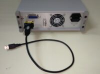
We internally use the Wiretek VE 488 as a USB-serial converter. The FTDI FT232RL converter chipset is used inside the converter cable.
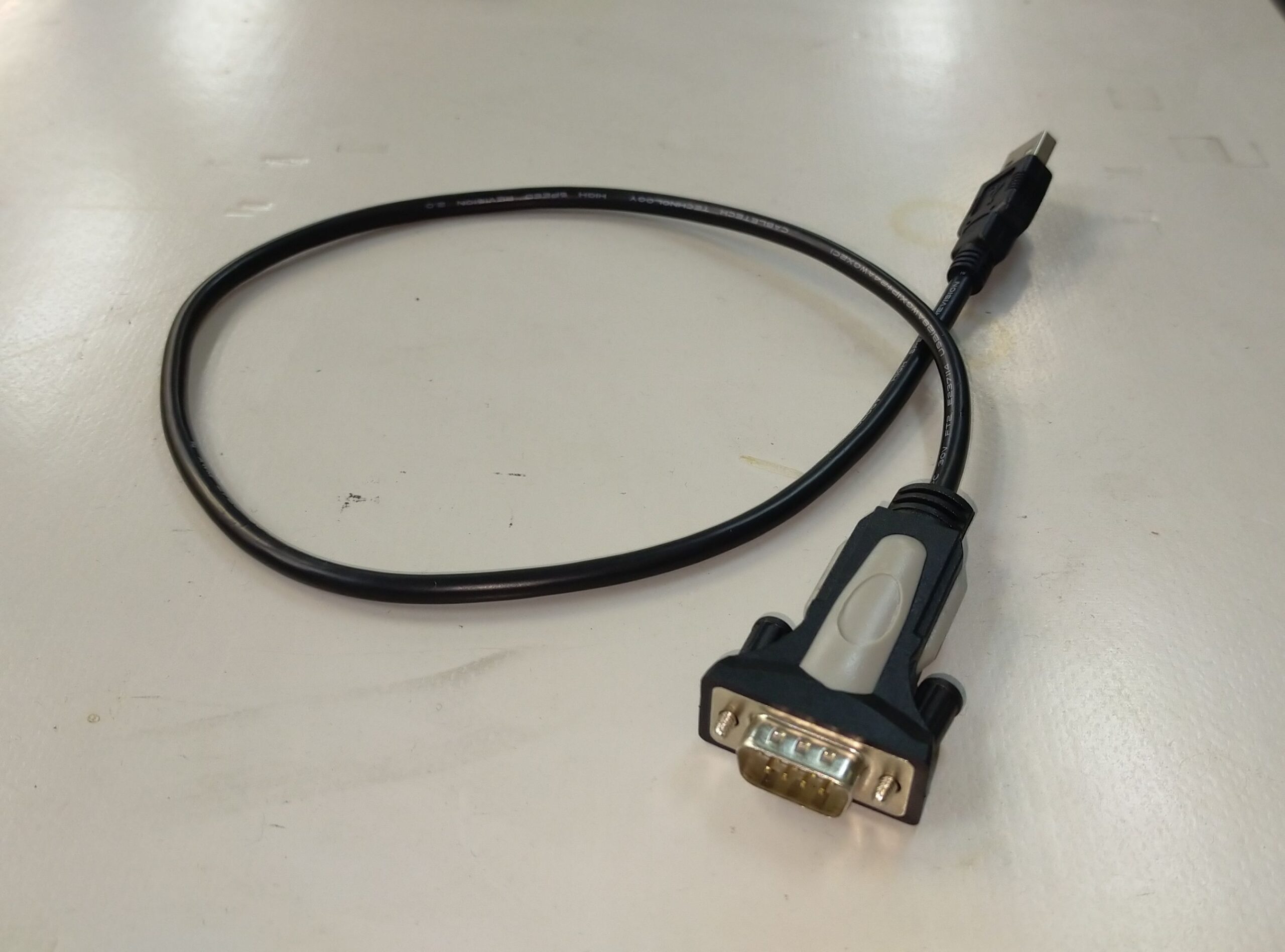
Figure 1: Wiretek VE 488 USB-serial converter.
In the past, we used several USB-serial converters based on Prolific PL2303 converter chipset. They are however no longer our first choice as we often suffered driver issue on Windows 10 environment. There are many external blog posts reporting the same issue, and they also suggest solutions. The solutions worked for us as well, so if you already have a converter based on the chipset, please refer to the following link to fix the issue.
In many cases, a DB9 female-to-female gender changer is also needed to connect the converter cable to a FiberLabs’ instrument (equipped with a DB9 male connector). This is because most USB-serial converters come with a DB9 male connector. Indeed, the Wiretek VE488 that we use also comes with a male connector.
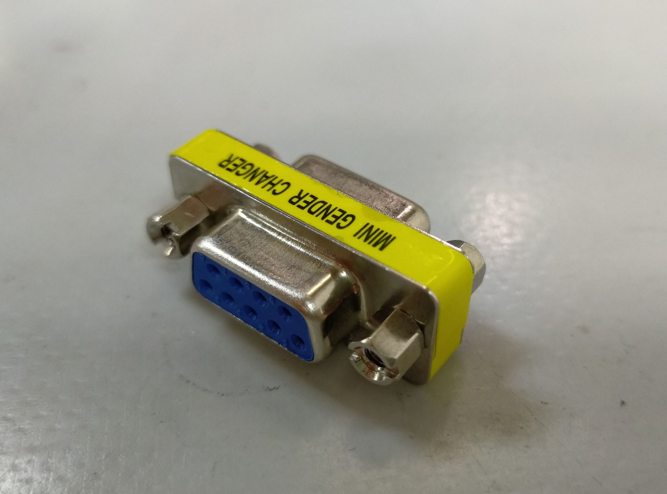
Figure 2: DB9 gender changer
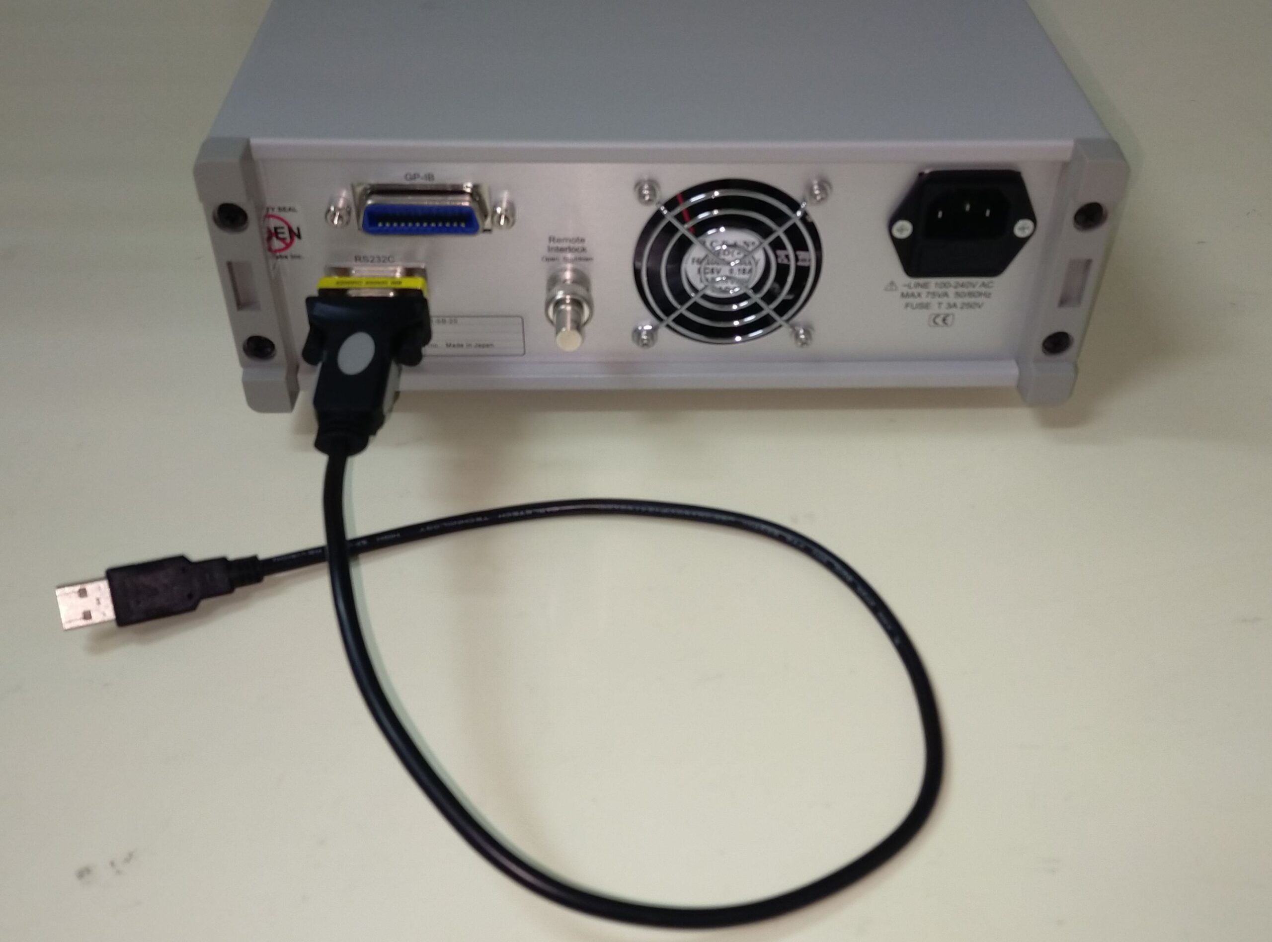
Figure 3: USB-serial cable and DB9 gender changer
attached onto FiberLabs’ bench-top chassis
Instead of using a female-to-female gender changer, we also use a female-to-female RS-232C DB9 straight-through cable. It is convenient when you cannot place your control computer near the instrument. Please make sure to choose a straight-through cable, not other types.
In principle, you should be able to use a combination of a male-to-female RS-232C DB9 straight-through cable and a DB9 female-to-female gender changer, though we have never tested it by ourselves.
link O-band PDFA and tunable filter for transceiver testing
The O-band transceivers have been extensively used for high-speed Ethernet. The primary reason is that dispersion compensation is much easier in the O-band than in the C-band. These transceivers are produced to meet an industry standard (e.g. IEEE), and some tests require boosting the optical signals. Unlike the C-band, however, fiber amplifiers are not commonly available in the market.
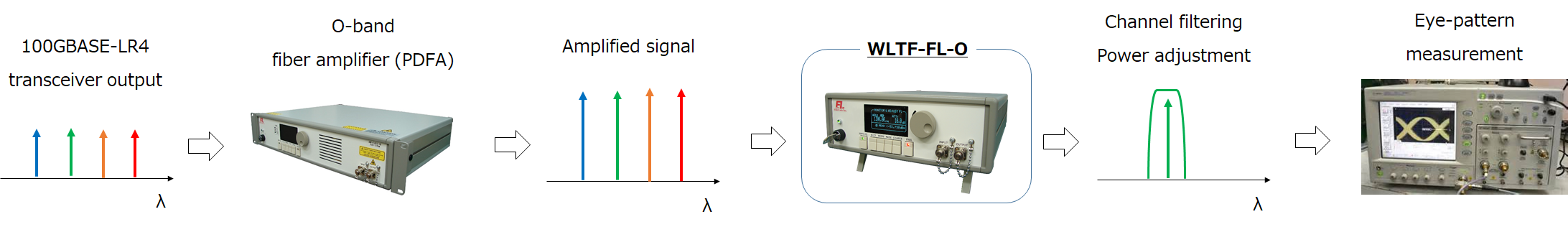
Here we propose one scheme that is useful for transceiver testing, in which PDFA and optical filters are combined.
One typical case where PDFA and tunable filter is eye pattern measurement by an oscilloscope. In many cases the output from a transceiver TX is too weak for oscilloscope measurement and optical boosting is required. A PDFA boosts the WDM signal, and one channel is sliced by a tunable filter. The tunable filter possesses a built-in attenuator, and the output power to an oscilloscope is automatically adjusted.
FiberLabs offers the following products related to this article. Please visit these pages if you are interested in this article.
link O-band optical amplifier for monitoring 100G Ethernet
This article shows an application of O-band optical fiber amplifier (PDFA) for enhancing monitoring capability of 100G Ethernet. It is shown that a PDFA allows for delayless and multiple replications of 100GBASE-LR4 signal for connecting multiple network monitoring appliances, by compensating the branching loss of an optical TAP (Test Access Point) and 1xN splitter.
Network monitoring is an essential task for a network operator. There are many schemes for network monitoring, and the use of an optical TAP (see Figure 1) is a preferred choice for high reliability and minimum service downtime. An optical TAP is a passive optical power splitter which possesses a very low failure rate; therefore the risk of failure is minimized. In addition, maintenance or failure in the mirrored link does not affect the service in the main link.
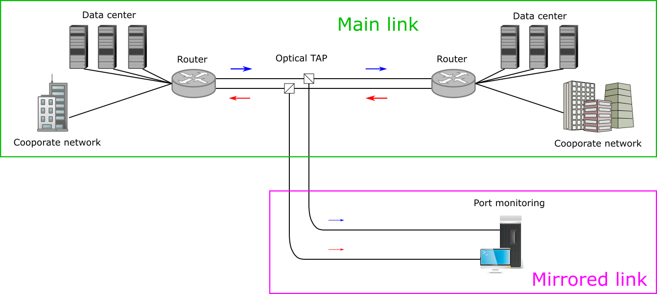
Figure 1: Network monitoring using optical TAP.
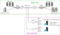
The growing demand for operating various internet services resulted in the need for detailed network monitoring (traffic monitoring, fault detection, deep packet inspection, etc.), and there are many cases where multiple monitoring appliances need to be connected. In such cases, the signal in the mirrored link may be re-boosted by an optical amplifier and divided by a splitter, as shown in Figure 2.
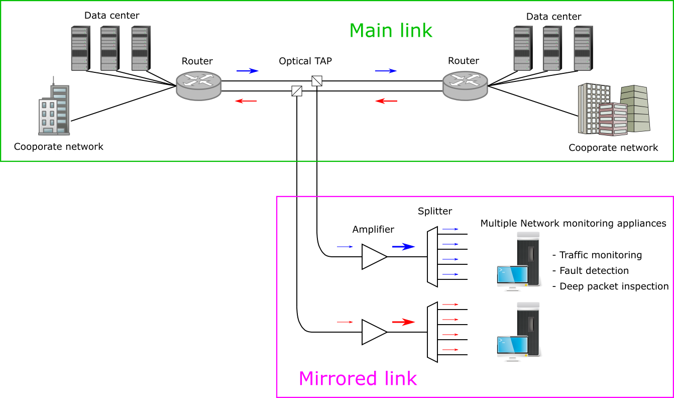
Figure 2: Connecting multiple monitoring appliances using optical amplifier and splitter.
The 100G Ethernet uses the O-band for optical transceivers, and thus Eribum-Doped Fiber Amplifier cannot be used. Instead, PDFA – which is much less known compared to EDFA – can be used in the 1310-nm wavelength range. In the following, we experimentally show that our PDFA (AMP-FL5611-OP15) can be used for connecting at least eight monitoring appliances in the mirrored link.
Our experimental setup is shown in Figure 3. The setup emulates: (1) the main link for actual data transmission, and (2) mirrored link for network monitoring.
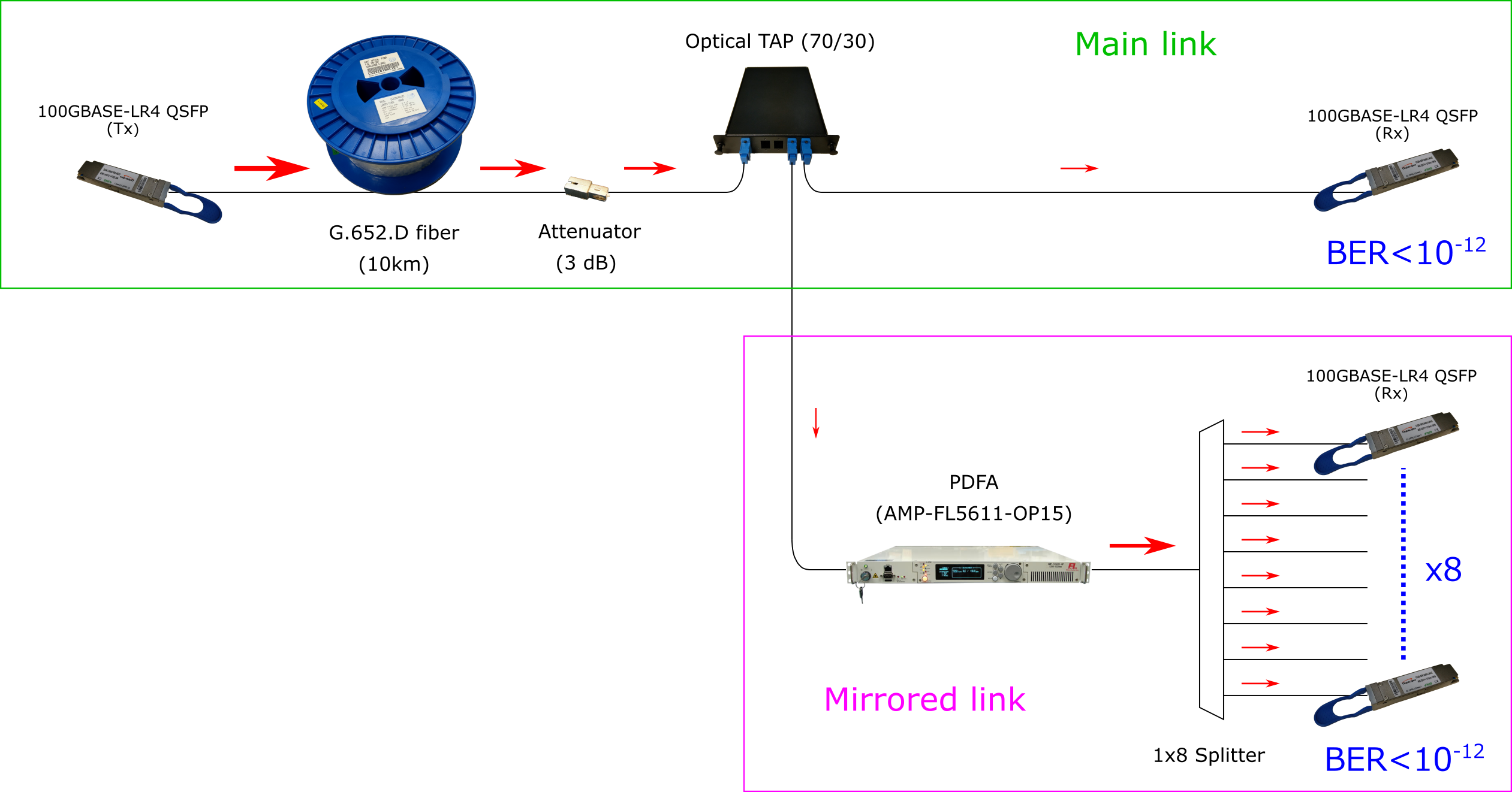
Figure 3: Experimental setup and measured BERs.
The main link had the following three components:
The total attenuation of these three components was about 9 dB at 1310 nm. The mirrored link was separated from the main link by the 70/30 TAP, and the TAP was followed by these two extra components:
These two components allows for re-boosting the signal and providing sufficient optical power to eight monitoring ports, such that each of the eight signals can be read by a standard 100GBASE-LR4 receiver.
The validation of this configuration was done by conducting a series of BER measurements for all the nine receiver ports (one main link and eight output ports from the splitter). The BER measurements were conducted using a 100GBASE-LR4 transciever (Gigalight GQS-SPO101-LR4C) and a QSFP optics checker (Gigalight 40G QSFP+ & 100G QSFP28 Optics Checker). The measured BERs were <10-12 for all the nine ports. In order to confirm that the system operates with margin, we added a 1-dB attenuator in the main link (before the TAP) and in the monitoring port (after the splitter); the BERs were still <10-12 for all the nine ports, showing that this configuration possesses a sufficient amount of margin.
The most important feature of this scheme is that the packet replication is done in the optical domain and thus does not include any O/E-to-E/O conversion. This feature leads to the following two important advantages:
The delayless replication may be of a huge benefit where signal delay needs to be minimized (e.g. financial trading). The second feature would secure potential future upgrade when 200G/400G-LR4 emerges in the market.
FiberLabs offers the following products related to this article. Please visit these pages if you are interested in this article.
link O-band optical preamplifier for 100G Ethernet
This technical article describes an application example of FiberLabs PDFA for enhancing the link budget of 100GBASE-LR4 transmission. We show that, by adding a FiberLabs PDFA as a preamplifier, the link budget can be increased by 7 dB.
The benefits of adding a preamplifier PDFA was evaluated by conducting a series of BER measurements in the following two conditions:
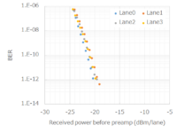
The experimental setup and results are summarized in Figure 1. The BER measurements were conducted using a 100GBASE-LR4 transciever (Gigalight GQS-SPO101-LR4C) and a QSFP optics checker (Gigalight 40G QSFP+ & 100G QSFP28 Optics Checker). A variable optical attenuator was used to change the signal power launched to the receiver or preamplifier. BERs were measured as a function of signal power before receiver (back-to-back), and as a function of power before preamplifier (with PDFA). The signal pattern was PRBS31.
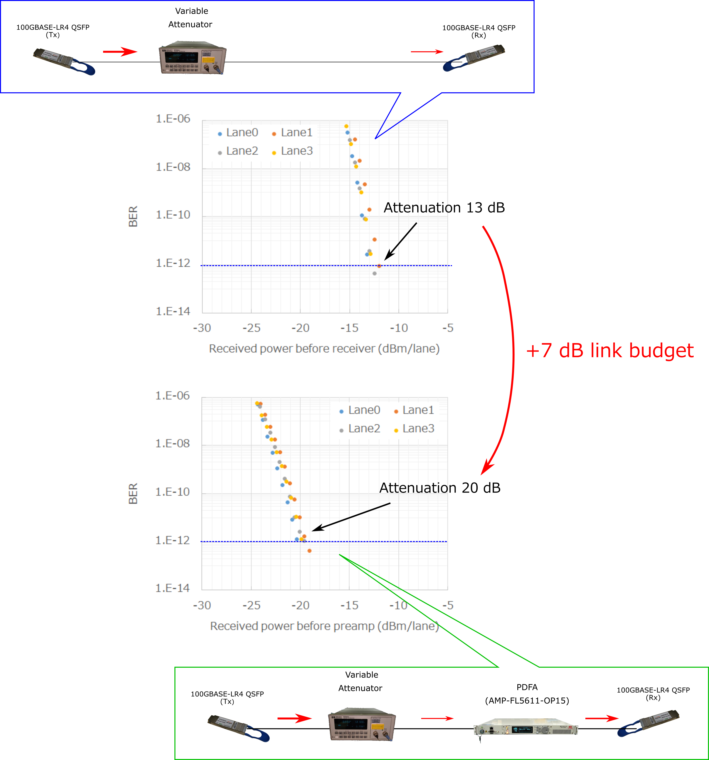
Figure 1: Setup of experiment and results.
With the addition of a preamplifier PDFA, the minimum power for meeting the IEEE specification (BER<10-12) was decreased from -12 dBm/lane to -19 dBm/lane, providing 7-dB improvement. The maximum attenuation for meeting the IEEE spec were 13 dB (back-to-back) and 20 dB (with preamp), showing that the link budget was increased by 7 dB.
The link-budget enhancement achieved by this preamplifier configuration is somewhat lower than the booster amplifier configuration. This is mainly because the BERs were limited by noise figure (i.e. ASE noise) of PDFA in the preamplifier configuration. We justify this assumption by our experimental observation that further increasing the preamplifier gain (>15 dB) did not result in BER improvement.
It is therefore preferred to use a PDFA in the booster configuration for best performance, while the preamplifier configuration may be preferred if a high signal power from a booster PDFA (~100 mW) is a concern.
FiberLabs offers the following products related to this article. Please visit these pages if you are interested in this article.
link O-band booster Optical Amplifier for 100G Ethernet
This technical article describes an application of FiberLabs PDFA for enhancing the link budget of 100GBASE-LR4 transmission. We show that adding a FiberLabs PDFA as a booster amplifier
The benefits of a booster amplifier was evaluated by conducting a series of BER measurements in the following two conditions:
The experimental setup and results are summarized in Figure 1. The BER measurements were conducted using a 100GBASE-LR4 transciever (Gigalight GQS-SPO101-LR4C) and a QSFP optics checker (Gigalight 40G QSFP+ & 100G QSFP28 Optics Checker). A variable optical attenuator was used to change the signal power to the receivers, and BERs were measured as a function of received signal power (each lane, not total power).
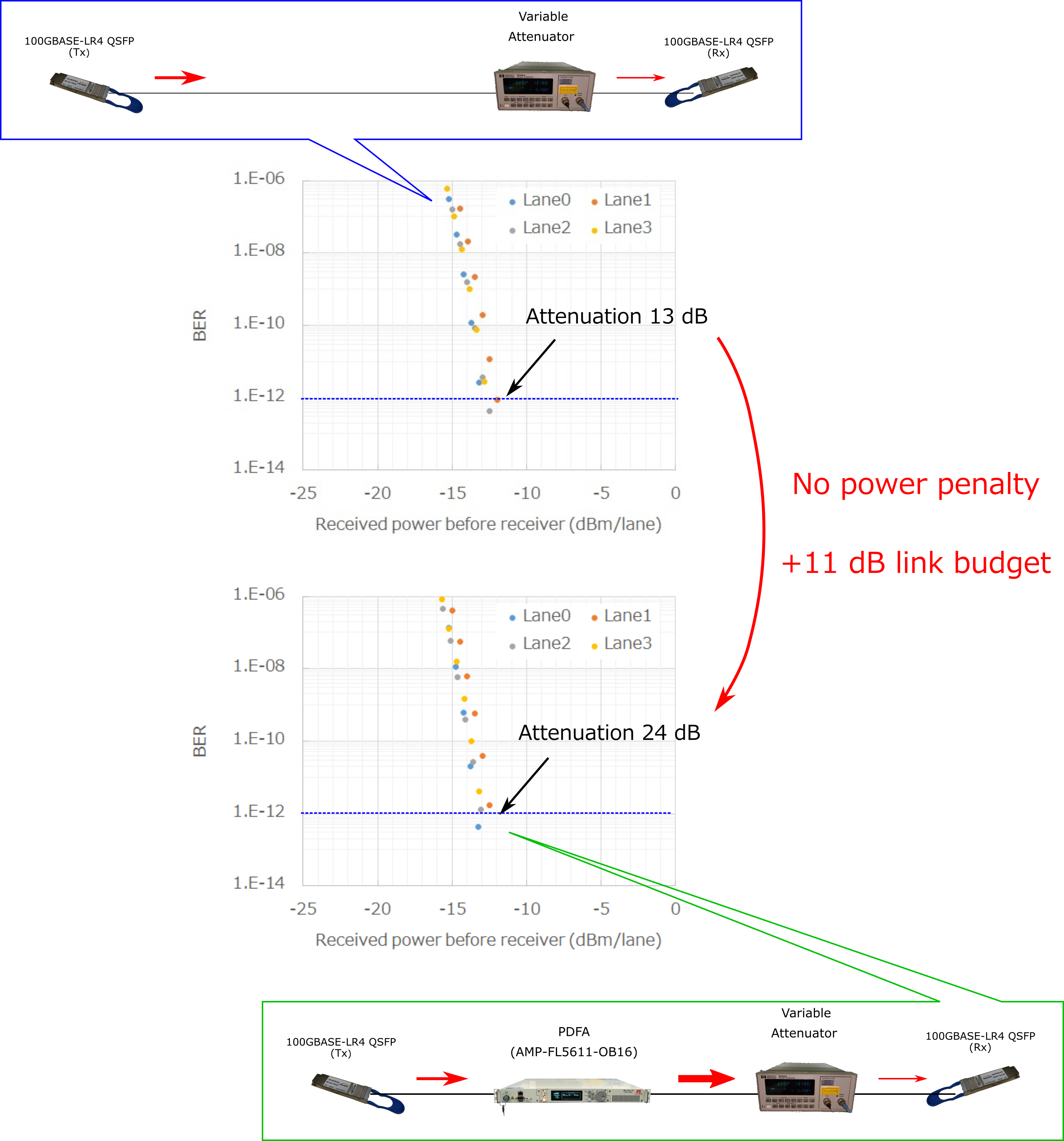
Figure 1: Setup of experiment and results.
Two graphs (receiver power vs BER) are almost identical even with the addition of booster PDFA, showing that the PDFA did not add power penalty. Of course, the link with PDFA accommodates higher attenuation as a result of amplification. The maximum attenuation for meeting the IEEE specification (BER<10-12) was increased from 13 dB to 24 dB, showing that the link budget was increased by 11 dB.
The high output power and low noise figure of a PDFA allowed the enhancement of link budget without power penalty. This scheme can also be applied to extended-reach transceivers (e.g. 100GBASE-ER4, 100G ER4-lite, and 100G 4WDM-20/40), as they are based on high-sensitivity receivers, and not high-output transmitters. The maximum reach may be extended to >60 km with the simple addition of a booster PDFA.
Other than link budget enhancement, the use of booster PDFA may hugely benefit transceiver testing (e.g. receiver stress test), or branching-loss compensation for network monitoring, etc.
So far, PDFA is the only practical choice if you need to simultaneously amplify the LR4 signal to a high power (>+15 dBm). SOA may be used as a preamplifier but not as a booster amplifier, as the saturation output power of SOA is typically below 10 dBm. Another critical reason an SOA cannot be used for this application is nonlinear effects, which result in significant BER degradation.
FiberLabs offers the following products related to this article. Please visit these pages if you are interested in this article.
link Optical Fiber Amplifier for 100G/400G Ethernet
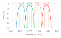
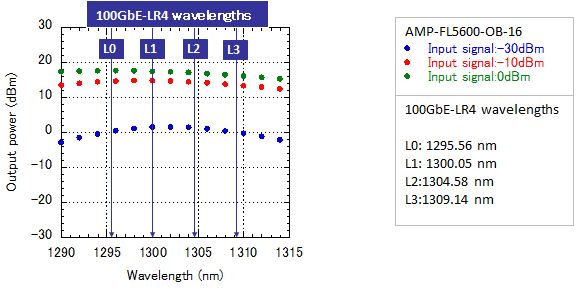
The 100GBASE-LR4 standard is defined by IEEE as an Ethernet interface for transmitting 100 Gigabit Ethernet (100GbE) frames over 10 km of conventional SMF, and it has been one of the fastest-growing Ethernet interfaces in the 2010s. 100GBASE-LR4 uses four wavelengths in the O-band (1260-1360 nm), referred to as either DWDM or LAN-WDM wavelengths, and each of the four wavelength lanes carries 25 Gbps signal to support 100 Gbps (25 Gbps x 4) data rate.
Table 1: IEEE 100GBASE-LR4 optical interface summary
| Min | Max | ||
| Transmitter wavelength (nm) | Lane 0 | 1294.53 | 1296.59 |
| Lane 1 | 1299.02 | 1301.09 | |
| Lane 2 | 1303.54 | 1305.63 | |
| Lane 3 | 1308.09 | 1310.19 | |
| Average launch power per lane (dBm) | -3.8 | 4.0 | |
| Average receive power per lane (dBm) | -10.1 | 4.0 | |
| Channel insertion loss (dB) | 6.3 | — | |
| Operating distance (km) | — | 10 | |
Praseodymium-Doped Fiber Amplifier (PDFA) is known to have its gain in the O-band, and the gain peak matches the 100GBASE-LR4 wavelengths. FiberLabs is the only manufacturer of O-band PDFA, and our PDFA features:
Typical amplification characteristics of AMP-FL56xx-OB-16 are shown below. Specifications of all PDFA products can be found via the following links.
PDFA’s superior optical characteristics are unrivaled by alternative schemes (e.g. Semiconductor Optical Amplifier (SOA) and Raman amplifier), providing a solid and versatile platform for amplifying 100GBASE-LR4 signal. Typical applications of FiberLabs’ PDFA for 100GBASE-LR4 are listed in the following.
We have done a couple of transmission experiments using a standard QSFP28 100GBASE-LR4 transceiver. By clicking the links above, you can get general ideas how PDFA works for each of the applications.
Figure 2 shows an example where PDFA is used for optical port mirroring. Two optical TAPs are inserted in the main network, and the splitting ratio is set to a low value (e.g. 90/10) in order to minimize the impact to the main traffic. Two PDFAs are placed in the mirrored port and compensate the loss induced by splitting. Indeed, PDFA enables a large output power without suffering signal distortion, and the output power out of the PDFAs can be larger than that of the main traffic. It is therefore possible to simultaneously provide sufficient input power to multiple network monitoring appliances (e.g. traffic monitoring, fault detection, and deep packet inspection…), or to deliver the duplicated packets to a remote site.
(Click here to see our technical article showing how PDFA can be used for this purpose)
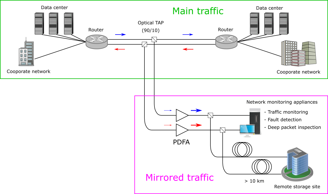
Figure 2: Application of PDFA for port mirroring in high-speed ethernet.
There are currently two commercially available options in amplifying 100GBASE-LR4 signal – PDFA and SOA. Both have pros and cons, and they are summarized in the following.
In general, PDFA surpasses SOA in optical performance. For example, FiberLabs’ PDFA offers higher maximum output power (+20dBm) and small signal gain (>25dB) than comparable SOA-based amplifiers. In addition, SOA cannot be used as a booster amplifier due to low output power and nonlinear optical effects.
On the other hand, SOA-based amplifier is generally smaller in size and is commonly used as a preamplifier in a 100GBASE-ER4 transceiver.
Table 2: O-band optical amplifier performance comparison summary
| FiberLabs’ PDFA | SOA | |
| Maximum output power | up to +20 dBm | < +10 dBm |
| Small signal gain | > 25 dB | ∼ 20 dB |
| Noise figure | < 7 dB | < 8 dB |
| Amplifier configuration | Booster/inline/pre-amplifer | pre-amplifier only |
| Footprint | Maximum 4 amplifiers in 19-inch chasis | Can be integratedinside transceiver module |
FiberLabs’ 19-inch 1U chasis can carry maximum four PDFAs, and a booster amplifier and pre-amplifier can coexist. This allows network operators to install PDFAs at only one side of the LR4 transceiver pair (see below), simplifying the installation and maintenance of reach extension.
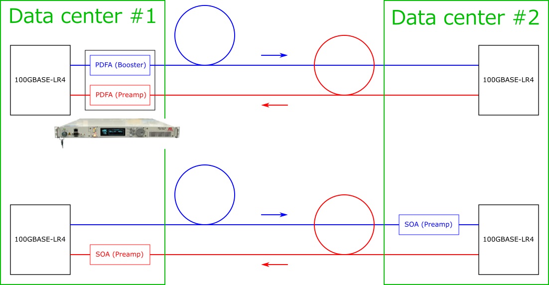
Schematic of one network configuration, where using PDFA has an advantage in extending the reach. PDFA is installed at only one side of the network, while SOA needs to be installed at both sides.
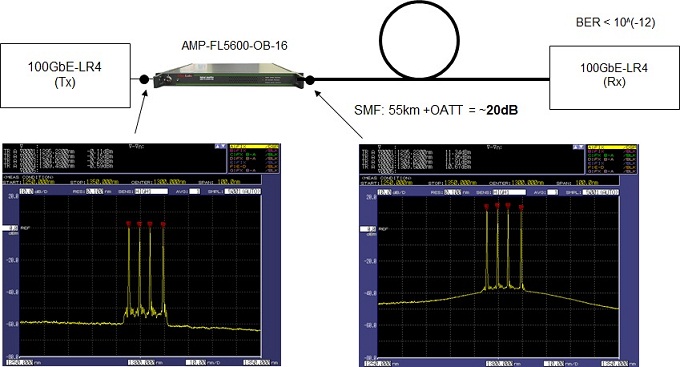
The following is an example, in which FiberLabs’ AMP-FL56xx-OB series PDFA is used as a reach extender for 100GBASE-LR4 transmission.
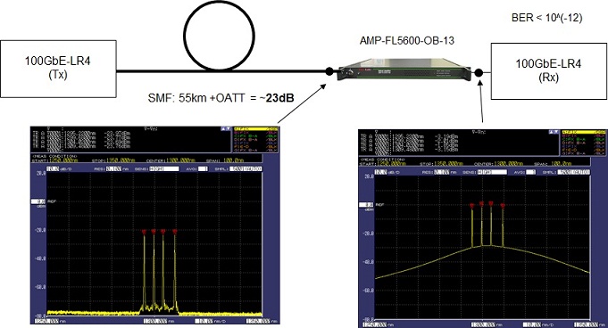
First, AMP-FL5600-OB-16 was used as the booster amplifier. The four signals from a 100GBASE-LR4 CFP were directly connected to the amplifier and were amplified by more than 10 dB per lane. Gain variation between the lanes was less than 1 dB. A link budget of 20dB was confirmed by using 55 km of SMF and an optical attenuator.
In the second scheme, a pre-amplifier configuration was used. The four wavelength signals were simultaneously amplified by AMP-FL5600-OB-13 to be within the range of receiver sensitivity after being attenuated by 23dB/lane using 55 km of SMF and an optical attenuator. A link budget of greater than 20 dB was confirmed.
Finally, AMP-FL5600-OB amplifiers were used as both the booster amplifier and pre-amplifier. A link budget of greater than 30dB was confirmed using 60 km of SMF and an optical attenuator.
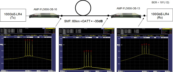
It should be noted that the reach is not limited to 60 km, but a larger link budget and further reach extension should be possible by using inline amplifiers in addition to the booster amplifier and pre-amplifier.
FiberLabs offers the following products related to this article. Please visit these pages if you are interested in this article.

link Uni-directional CWDM amplifier: installation example
CWDM transmission enables low-cost WDM transmission using uncooled laser diodes. It is often the case that the eight long-wavelength channels, from 1471 to 1611 nm, are chosen. This is because the loss of silica optical fibers are lower than the other eight short-wavelength channles. The transmission distance is, still, typically limited up to 70km, and one reason is the lack of appropreate optical amplifiers in the S-band (i.e. 1471, 1491, 1511nm CWDM channels).
FiberLabs possesses S-band amplification technology enabled by in-house fluoride fiber. It allows us to produce a fiber amplifier working from 1471nm to 1611nm. Below is a schematic of how our CWDM booster amplifier AMP-FL5701-B8 is used in the uni-directional configuration. The link budget is increased by 10 dB by the addtion of the booster amplifier, extending the maximum transmission distance up to 130 km.
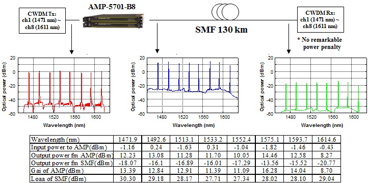
Figure 1: Increasing link budget using eight-wavelength CWDM booster amplifier
In addition to the above configuration using a booster amplifier only, an in-line amplifier may be combined. Figure 2 schematically shows an CWDM tranmission scheme where our CWDM in-line amplifier AMP-FL5701-I8 is used combined with AMP-FL5701-B8. The transmission distance can be further increased by this addition.
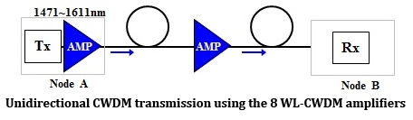
Figure 2: Combination of booster and in-line amplifier
If you do not need such a wide bandwidth using the eight wavelengths, it may be an option to use only the four long-wavelength channels, from 1531 to 1611 nm. Below is a schematic of how our four-wavelength CWDM booster amplifier AMP-FL5701-B4 and in-line amplifier AMP-FL5701-I4 are used in the uni-directional configuration.
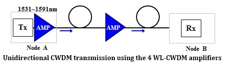
Figure 3: Increasing link budget using four-wavelength CWDM amplifier
FiberLabs offers the following products related to this article. Please visit these pages if you are interested in this article.